4.3. Calibration
4.3.1. Camera Intrinsic Calibration
The Active Camera has undergone intrinsic calibration prior to leaving the factory. The following method is provided for developers to recalibrate when necessary.
Pinhole cameras can cause significant distortion in images, with the main types of distortion being radial and tangential.
This module offers a camera intrinsic calibration tool based on the principles of Zhang’s calibration method.
Developers can follow the tool’s instructions to photograph a calibration target (sample patterns provided in this module can be used for creation) at various angles to calibrate the camera, thereby providing the necessary camera intrinsics and distortion coefficients for other modules.
The following video provides a real-time demonstration of the calibration field’s camera intrinsic calibration, primarily using the hardware configuration of
| Computing Platform | CPU: Intel® Core™ i5-1135G7 @ 2.40GHz × 8 MEM: 16GB |
| Sensor | AC1 |
Video Data: AC1 Camera Intrinsics Calibration data
Source Code: AC1 Camera Intrinsics Calibration code
4.3.2. Camera to LiDAR Calibration
The Active Camera has been calibrated from camera to LiDAR before leaving the factory. The following method is provided for developers to recalibrate when necessary.
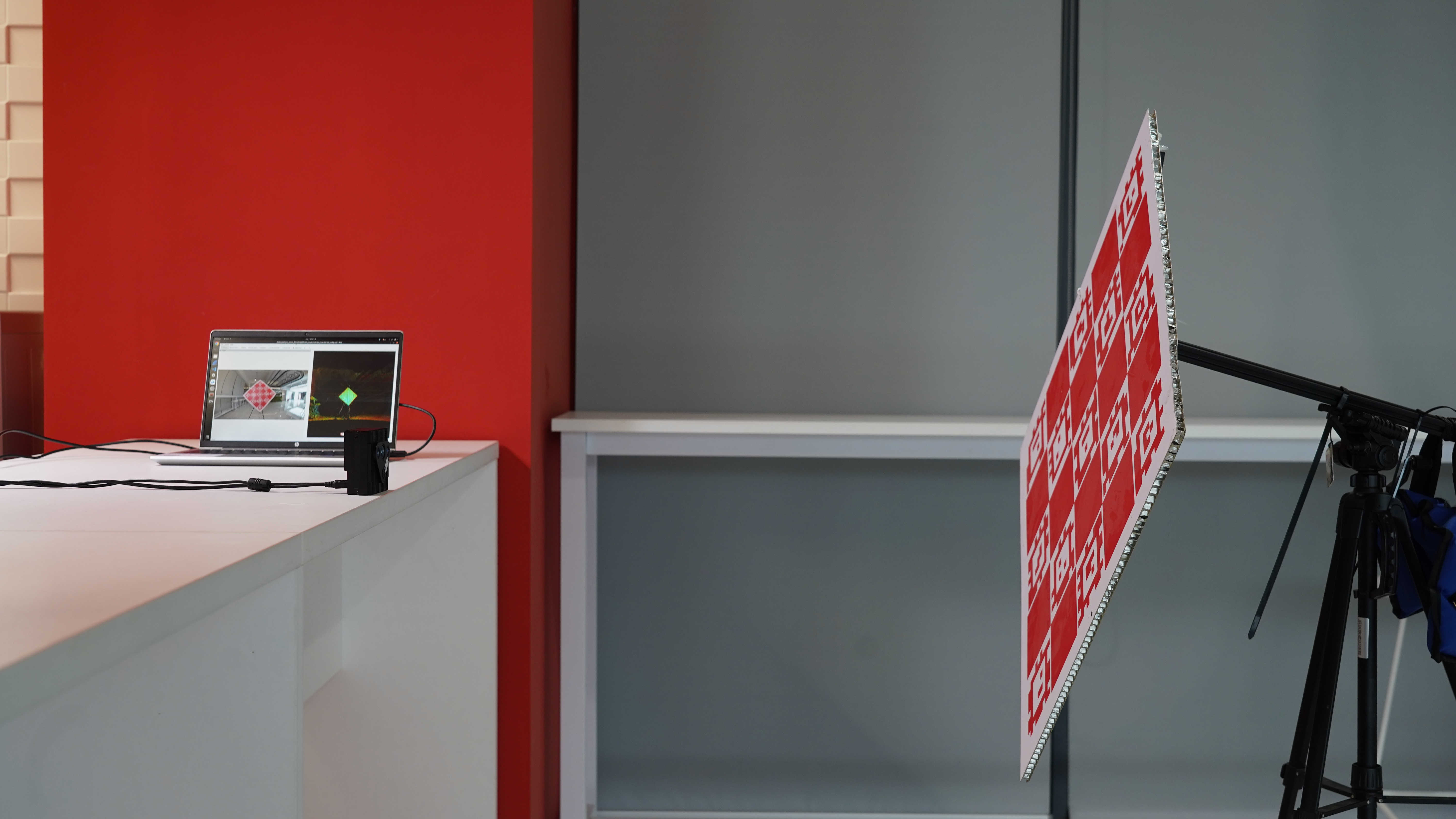
This module provides a camera-LiDAR calibration tool, reusing the calibration target from the camera intrinsic calibration to estimate the pose of the target for both the camera and the LiDAR separately, in order to provide the extrinsic parameters required by other modules.
During calibration, please ensure that the target is within the FOV of both the image and the point cloud, and try to keep the AC1 stable to avoid calibration errors due to sensor jitter.
Video Data: AC1 Camera to LiDAR Calibration data
Source Code: AC1 Camera to LiDAR Calibration code
4.3.3. Camera to IMU Calibration
The Active Camera has been calibrated from camera to IMU before leaving the factory.
The following method is provided for developers to recalibrate when necessary.
This module provides a camera-IMU calibration tool, reusing the calibration target from the camera intrinsic calibration to estimate the pose of the target for the camera from different angles.
Combining IMU motion data and applying hand-eye calibration methods, it calculates the camera-IMU extrinsic parameters required by other modules.
During calibration, please ensure that the target is within the FOV of the image, and try to keep the AC1 stationary to avoid calibration errors due to sensor jitter.
Video Data: AC1 Camera to IMU Calibration data
Source Code: AC1 Camera to IMU Calibration code
4.3.4. AC1 Sensor to Mobile Wheeled Platform Extrinsic Calibration
This module provides extrinsic calibration (angle calibration) for the AC1 to a mobile wheeled platform.
This module requires the prior recording of two sets of data: one set of data for driving at a constant speed along a straight line, and one set of data for rotating at a constant speed around a fixed axis.
Developers should follow the tool’s operational instructions, start the project, and then play these two sets of data in sequence.
After completing the calibration, the angle extrinsic parameters from the sensor to the mobile wheeled platform are output.
The translation part needs to be measured by the developer and then filled into the calibration file.
Video Data: AC1 to Wheel Platform Calibration data
Source Code: AC1 to Wheel Platform Calibration code
4.3.5. AC1 Sensor to Robotic Arm Extrinsic Calibration
This module provides extrinsic calibration between AC1 and the robotic arm (with AC1 fixed at the end-effector).
By combining the end-effector pose of the robotic arm with point cloud registration results, the hand-eye calibration method is employed to perform AC1-robotic arm extrinsic calibration.
During calibration, the robotic arm needs to be controlled to move along different directions.
Upon completion, the program outputs the extrinsic parameters from AC1 to the robotic arm’s end-effector.
Video Data: AC1 to Robotic Arm Calibration data
Source Code: AC1 to Robotic Arm Calibration code